 Instagram
 Twitter
 Github
 Email
Email Toggle Dark Mode
Loading Title
Loading a very long description that you cant see

How did it get to the point where Broadcom GUI App needed to be reverse engineered?
Well, we are curently developing a device in which we want to use one of these sensors. They are very precise and fast which is exactly what we need.
Our Problems started after realising that this sensors SPI Communication is proprietary and broadcom only provides drivers for some ARM Cortex uCs.
Decided Solution was to use one of their refernce Boards and integrate that into our Project.
The board below is the refernce board we decided on.
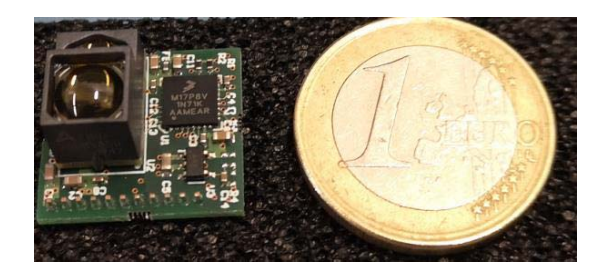
Source: https://docs.broadcom.com/doc/AFBR-S50-RD-AN
As this board uses NXP CPU we needed a proper programmer to flash the prebuilt binary (located inside the install folder of the Explorer GUI). We were unable to obtain one such programmer as they were unavailable everywhere we looked at.
After some time I stumbled upon OpenOCD Project and I was excited to be finally able to flash the Firmware to this Board.
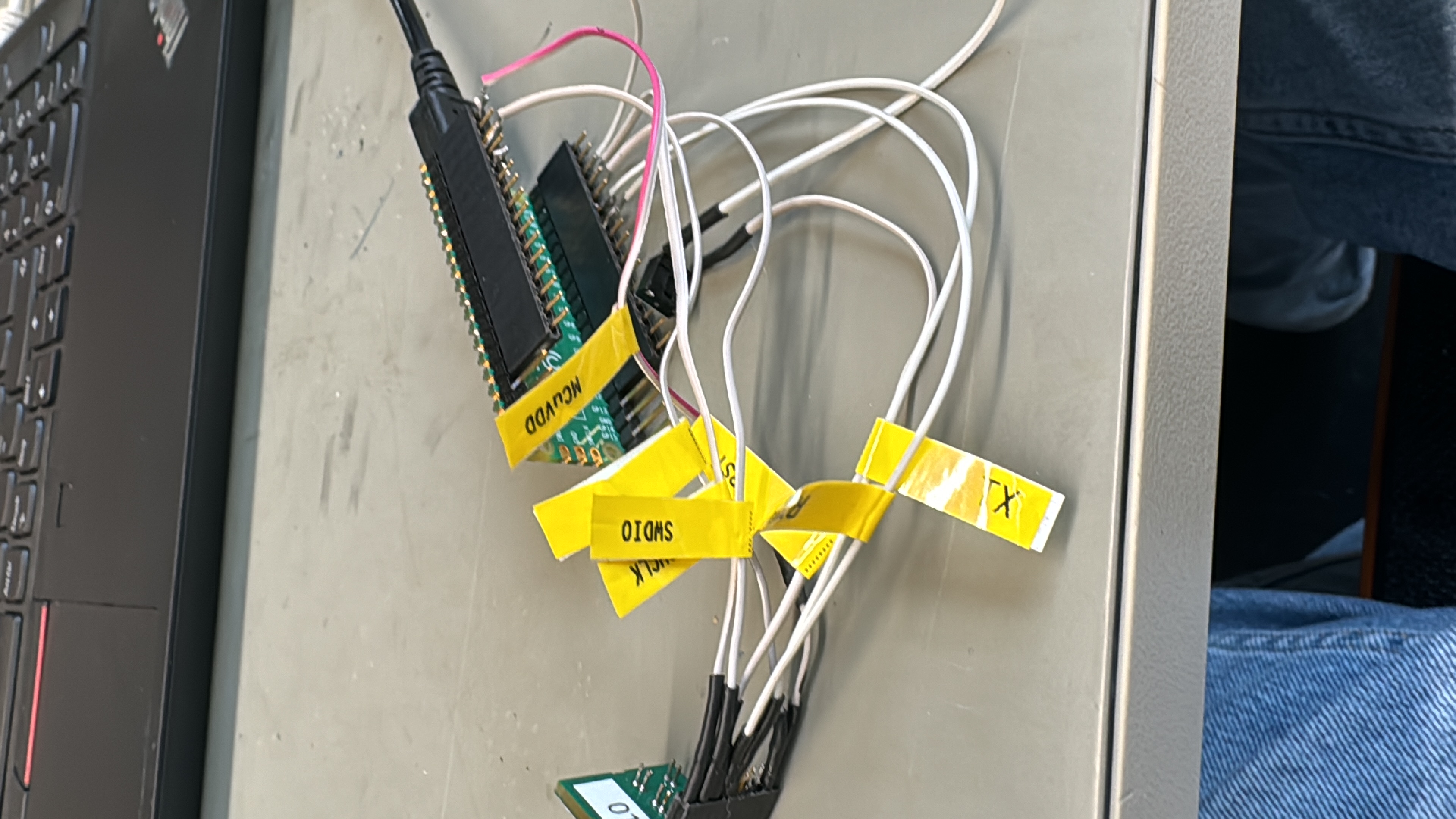
And it worked! After wiring the Board to the Pico running Debugprobe firmware I was able to flash the board.
Pico and Reference Board were connected like so:
| Reference Board | Pico Debugprobe |
| GND | GND |
| 5V | VUSB |
| SWCLK | GPIO 2 |
| SWDIO | GPIO 3 |
| LPUART0 RX | GPIO 4 |
| LPUART0 TX | GPIO 5 |
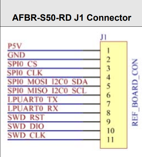
(Refenrce Board Connector)
After running
> openocd -f interface/cmsis-dap.cfg -f target/kx.cfg -c "program AFBR.S50.ExplorerApp.v1.6.5_KL17z_UART.bin verify reset exit"
to flash the firmware onto the NXP Chip Openocd returned a message telling me that flash has been uploaded and verified!
Exciting right, the GUI should now work, right? WRONG
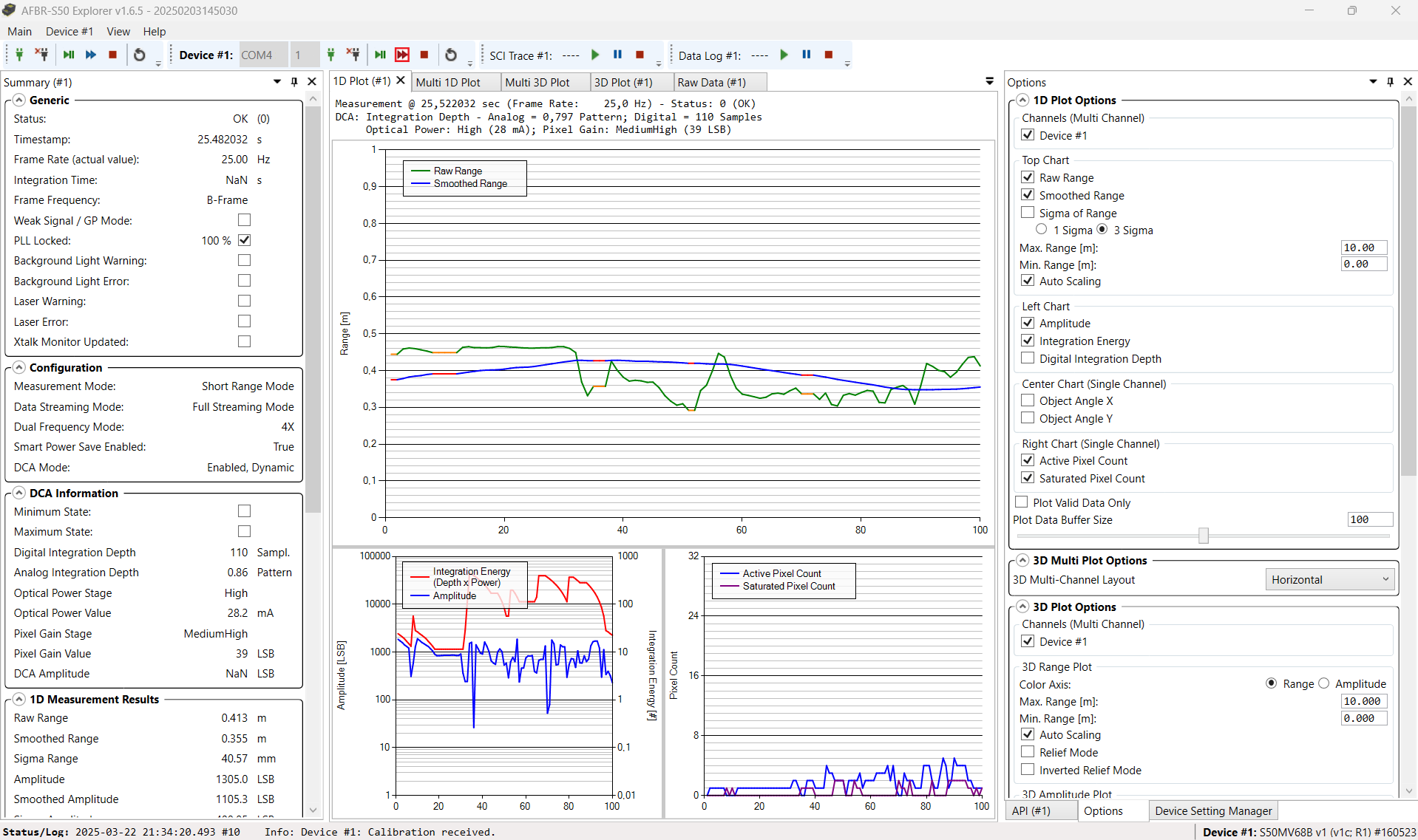
Trying to use Explorer GUI to connect to the Board I was met with this error:
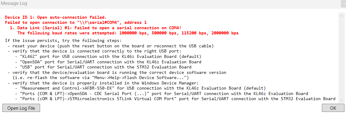
At first I thought my connections were wrong but nope, they were all okay. I tried their provided Python SCI example script and it worked first time... I was getting range and amplitude data with no problems.
That ment the Problem lied somwhere in GUI Explorer App.
The thing that made me somwhat sceptical about that is that connecting the Reference Board using standard FTDI Cable for some reason worked and the GUI had no problems communication with the sensor.
I still did not understand why this would be a problem, at the end both COM Ports (Debugprobe and FTDI Cable) are VCPs (Virtual Com Ports)
Here I decided to analyse what is happening when App tries to communicate with the board over Pico. Looking at my Osciloscope I could not see any data flowing in any dierction when the GUI tries to connect and communicate.
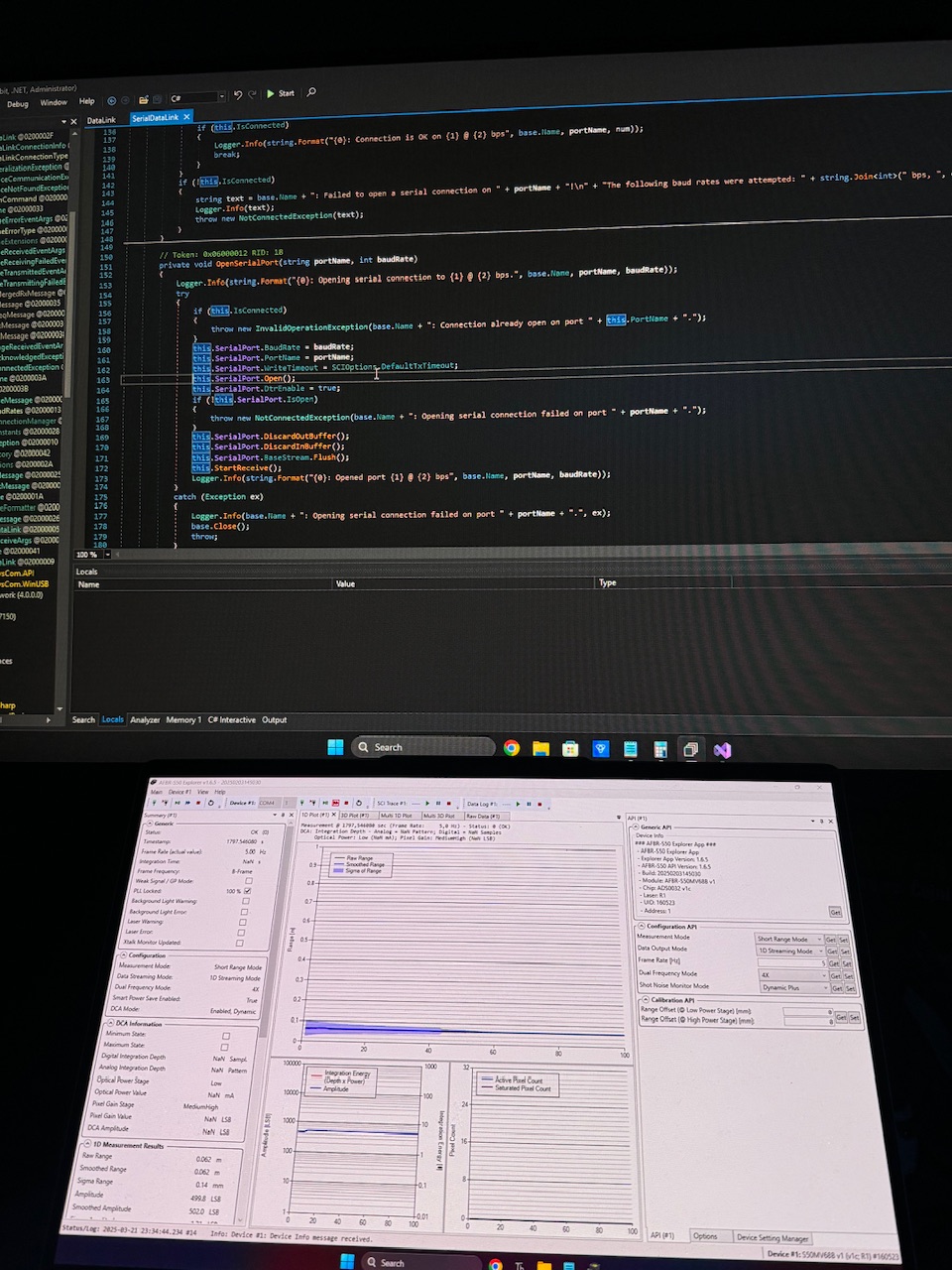
I decided to 'hack' into the App to see what is happening. Their App is Writen in C# .NET so it was not hard to Attach exteral Debuger to it and analyse the functions.I used dnSpy for this.
After many hours It came to one single line
> this.SerialPort.DtrEnable = true;
Turns out Dtr Signaling is not set by default in the GUI App and Windows then simply decides not to push data over UART.
After patching the app I was happy to see the GUI finally be able to communicate with the Board!
Update: I opened a Github issue over on their official Repository and this is the reason they gave for why the App is written like it is.
They said that they might consider implemening Dtr Signaling in future version of their GUI.
If you need more info, please contact me over email. My email is available in the sidebar of this Page.